Some points:
muld is forced to wait a cycle.
ld, is not fetched until after
the branch leaves ID.
Time 0    1    2    3    4    5    6    7    8    9    10   11   12   13   14   15   16   17   18   19   20   21   22   23   24   25   26   27   28
muld IF   ID   5:A1 5:A2 5:A5 5:A4 5:WB
addd      IF   ID   3:RS 3:RS 3:RS 3:RS 3:A1 3:A2 3:A3 3:A4 3:WB
muld           IF   ID   6:RS 6:RS 6:RS 6:M1 6:M2 6:M3 6:M4 6:WB 6:WB
subd                IF   ID   4:RS 4:RS 4:RS 4:A1 4:A2 4:A3 4:A4 4:WB 4:WB
loop:
ld                       IF   ID   2:EX 2:MI 2:WI                                                                       IF   ID
subd                          IF   ID                            3:RS 3:RS 3:A1 3:A2 3:A3 3:A4 3:WB
ld                                 IF                            ID   1:EX 1:MI 1:WB
subd                                                             IF   ID   4:RS 4:RS                4:A1 4:A2 4:A3 4:A4 4:WB
ld                                                                    IF   ID   2:EX 2:MI 2:WB
subd                                                                       IF   ID                  3:RS                     3:A1 3:A2 3:A3 3:A4 3:WB
subi                                                                            IF                  ID   1:EX 1:MI 1:WB
addi                                                                                                IF   ID   2:EX 2:MI 2:WB
bnez                                                                                                     IF   ID        1:EX 1:MI 1:WB
Time 11   12   13   14   15   16   17   18   19   20   21   22   23   24   25   26   27   28
muld
addd 3:WB
muld 6:WB 6:WB
subd 4:A4 4:WB 4:WB
loop:
ld                                                               IF   ID
subd      3:RS 3:RS 3:A1 3:A2 3:A3 3:A4 3:WB
ld        ID   1:EX 1:MI 1:WB
subd      IF   ID   4:RS 4:RS                4:A1 4:A2 4:A3 4:A4 4:WB
ld             IF   ID   2:EX 2:MI 2:WB
subd                IF   ID                  3:RS                     3:A1 3:A2 3:A3 3:A4 3:WB
subi                     IF                  ID   1:EX 1:MI 1:WB
addi                                         IF   ID   2:EX 2:MI 2:WB
bnez                                              IF   ID        1:EX 1:MI 1:WB
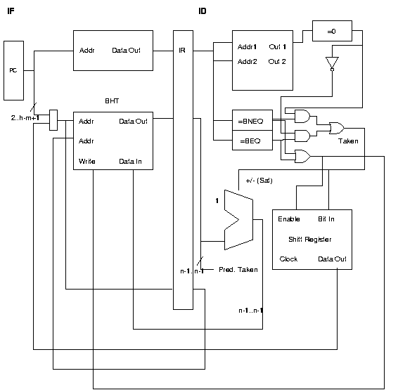
The BHT has a separate read and write port (so that one entry can be read while another is updated). The BHT address is the concatenation of h-m PC bits and m bits from the shift register. The BHT entry and the BHT entry address are clocked into the IF/ID latch.
The prediction is made in the ID stage simply by looking at the most significant bit of the BHT entry. An updated BHT entry is generated by adding or subtracting 1, based on the branch outcome. (In any real branch prediction scheme we would not know the outcome until several cycles later.) Using the address in the IF/ID latch, the updated entry is written to the BHT (at the end of ID) using the address from the latch. (It's important to write the entry to the same address it was read from, of course.)
The shift register is updated at the end of ID. The register shifts only if the "enable" line is asserted.
The solution below would have received full credit, but it does have
a problem: If there are two consecutive branches, the shift register
value used for the second branch will not be correct. How could
this problem be fixed? Also, how would the design be changed if
the "taken" signal were available only after ID?


| David M. Koppelman - koppel@ee.lsu.edu | Modified 28 Apr 1997 18:50 (23:50 UTC) |