 beqz r10,A
 add r3,r2,r1
A:
 addi r4,r5,#12
 beqz r10,B
 addi r4,r6,#13
B:
 addi r5,r4,#14
 beqz r10,C
 addi r5,r7,#15
C:
 addi r8,r5,#16
 beqz r10,D
 addi r8,r2,#17
D:
 addi r9,r8,#18
(Note that a good programmer would implement the code fragment above differently.)
Notice that all branches use the some register. That makes it easy to replace all branches with a single PM:
 pm R10, 0xFF, 0xAA
 add r3,r2,r1
 addi r4,r5,#12
 addi r4,r6,#13
 addi r5,r4,#14
 addi r5,r7,#15
 addi r8,r5,#16
 addi r8,r2,#17
 addi r9,r8,#18
        0  1   2   3   4   5   6   7
 beqz  IF  ID  EX  MEM WB
 add	   IF  ID  __
A:
 addi		       IF  ID  EX  MEM WB
 beqz			   IF  ID  EX  MEM WB
The time between the beqz instructions is five cycles, the number of
instructions executed is 2. This sequence repeats four times in the
entire code fragment, and the sequence takes another four cycles
to complete (for the pipeline to drain. So:
IC = 2 × 4 = 8.
t / cycles = 2 × 5 + 4 = 24.
CPI = 24 / 8 = 3
With the PM instruction there are no stalls, so the total execution time is 9 + 4 = 13 cycles. When r10=0, four instructions are nulled, so IC = 5. Then
CPI = 13 / 5 = 2.6
The execution time is almost twice as good (which is what counts), and the CPI is slightly better.
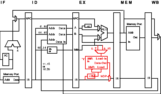
As shown in red below, add an eight-bit shift register to the EX stage. When a PM instruction is in EX, the appropriate 8-bit execution mask (from the immediate portion of the ID/EX latch) is loaded into the shift register.
At every cycle, the least significant bit of the shift register is checked. If it's zero, the instruction in the EX stage is nulled by replacing it with a NOP. (This works because instructions do not change "state" until the MEM and WB stages.) At the end of the cycle the shift register is shifted right (removing the least significant bit) with a 1 shifted into the left side.

Things would be simplest if only arithmetic (including logical and compare) instructions were allowed after a PM. So a reasonable restriction is that the PM works as described above until a non-arithmetic instruction is encountered, in which case the remainder of the mask is set to ones (i.e., the PM instruction is cancelled) or reloaded with a new mask if the non-arithmetic instruction is another PM.


| David M. Koppelman - koppel@ee.lsu.edu | Modified 4 Mar 1997 19:37 (1:37 UTC) |